social

pop

Infrared distance measurement: Interfacing Infrared distance sensor

Interfacing infrared ranger module and object detection using GP2D120 IR sensor and PIC microcontroller

Functioning of the IR Ranger Module

There are several ways of Measuring range. The easiest way is by using sound waves where ultrasonic sound is fowarded, and is reflected when hit by an object and the time it takes to reflect back is measured. Sounds waves do not travel fast, and can be measured by present day equipment.
However, in the case of infrared light, the time it takes to hit an obstacle and reflect back can not be measured because infrared light travels fast.

An IR transmitter emits infrared light to the object in front, by passing through a condense lens. Refraction occurs once the light hits the surface of the object. Part of the refracted light falls on the receiver end which is then passed to another lens and processed by an array of photo-transistors.
Hence, the position in which the light falls can be used to calculate the distance of an obstacle from the transmitter.

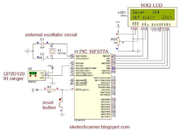
Circuit diagram of Infrared distance sensor and measurement.

The circuit diagram consist of the following components and is shown in the figure below:

  • PIC 16f877A microcontroller
  • GP2D120 Infrared distance Sensor
  • 16X2 LCD
  • Resistor
  • 8Mhz Oscillator 
  • variable resistor
  • capacitor  
  • +5V power supply
Infrared distance sensor

Infrared sensor pins description


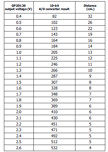
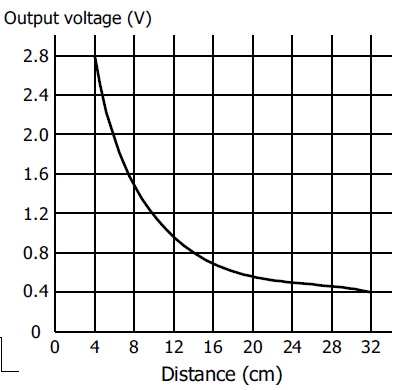
Relationship between output Voltage,ADC Result and distance

The table and the graph below shows the various relationship between output voltage and the distance obtained from the analog to digital converter values. This values are very important in programming ( interfacing) this module.
Relationship between voltage, ADC and distance
Distance variation with respect to voltage

Simulated Code

The code used to interface this module is shown below.

  sbit lcd_RS_Direction at TRISB0_bit;
  sbit lcd_EN_Direction at TRISB1_bit;
  sbit lcd_D4_Direction at TRISB2_bit;
  sbit lcd_D5_Direction at TRISB3_bit;
  sbit lcd_D6_Direction at TRISB4_bit;
  sbit lcd_D7_Direction at TRISB5_bit;

  sbit lcd_RS at RB0_bit;
  sbit lcd_EN at RB1_bit;
  sbit lcd_D4 at RB2_bit;
  sbit lcd_D5 at RB3_bit;
  sbit lcd_D6 at RB4_bit;
  sbit lcd_D7 at RB5_bit;

  int y;
 void read_adc()
{
  ADCON0=0b11001001; // EN internal RC                                                 //OSC & AN1, wait                                         //conversion, power ADC
  ADCON0.GO=1 ;   //  Conversion in progress
  while(ADCON0.GO);   //  Wait until                                                      //conversion is complete
  y=(ADRESH*4)+(ADRESL/16); // convert                                                    //10bit to ADC value
}

void lcd_config()
{ lcd_Init();
  lcd_cmd(_lcd_clear);
  lcd_cmd(_lcd_cursor_off);
  }
  void main() {
int x;  char text[16];      char u[16];

TRISA=0XFF;
TRISB=0X00;
PORTB=0X00;

 lcd_config();
 while(1)
 {
 lcd_out(1,1,"Data= ");


 read_adc();
 WordToStr(y,text);
 lcd_out_cp(text);
 delay_ms(200);
 x=(2914/(y+5))-1; // conv ADC to cm
 lcd_out(2,1,"obj dist=");
  lcd_out(2,15,"cm");
 WordToStr(x,u) ;
 lcd_out(2,10,u);
 delay_ms(2000);
 }
 }

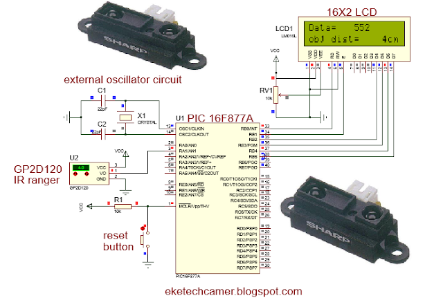
GP2D120 interfaced with PIC 16F8771A

Proteus  simulation of infrared distance sensor
Download File(proteus+code) will be available soon. Remain connected
Popular posts from this blog

PAST GCE QUESTIONS AND SOLUTIONS

 GCE PAST QUESTIONS AND SOLUTIONS TECHNICAL GCE ITVE and GCE ATVE Questions and Answers DOWNLOAD All ELECTRICAL POWER SYSTEM   DOWNLOAD All ELECTRONICS   DOWNLOAD All AIR CONDITIONING DOWNLOAD All MECHANICAL MANUFACTURING DOWNLOAD All AUTOMOBILE MECHANICS DOWNLOAD All SHEET METAL DOWNLOAD All WOOD WORKS    DOWNLOAD All BUILDING CONSTRUCTION DOWNLOAD All TOPOGRAPHY DOWNLOAD All CIVIL ENGINEERING DOWNLOAD All COMPUTER SCIENCE   DOWNLOAD All ICT DOWNLOAD All  ICT DOWNLOAD All CHEMICAL ENGINEERING DOWNLOAD All TOURISM DOWNLOAD All ACCOUNTING DOWNLOAD All  ICT DOWNLOAD All MATHEMATICS DOWNLOAD All LAW DOWNLOAD All ENGINEERING SCIENCE GENERAL EDUCATION GCE QUESTIONS AND SOLUTION DOWNLOAD All MATHEMATICS DOWNLOAD All FURTHER MATHEMATICS DOWNLOAD All ADDITIONAL MATHEMATICS DOWNLOAD All PHYSICS DOWNLOAD All BIOLOGY DOWNLOAD All HUMAN BIOLOGY DOWNLOAD All  ICT DOWNLOAD All CHEMISTRY DOWNLOAD All GEOGRAPHY DOWNLOAD All ECONOMICS DOWNLOAD All HISTORY D...

Intermediate switch connection and wiring diagram

Intermediate switch An intermediate switch is a switch which permits the control of a lighting point from three positions. In order to control this lighting point from the three positions, the intermediate switch is connected together with two other 2-way switches. Application: it can be used in lighting a room or hall having 3 entrances , it can also be used in long corridors and staircases. We shall be looking at these connections. Connection diagram of intermediate switching Below is an illustration of the connection. The brown lines indicated on the diagram are the switching contacts. The switch labelled 2 is an intermediate switch . The figure below is the configuration of an intermediate switch. The switch labelled 1 and 3 in the first diagram are two-way switches.  Click here to know more about two-way switches . ON and OFF positions of intermediate switching ON positions OFF positions Staircase wiring layout using an inte...

GCE QUESTIONS AND SOLUTIONS FOR ELECTRICAL POWER SYSTEMS

 DOWNLOAD GCE PAST QUESTIONS AND SOLUTIONS FOR EPS POWER ELECTRONICS  Download 1     Download 1b Download 2     Download 2b      Download 2C Download 3 AUTOMATIC CONTROL OF ELECTRICAL MACHINES Download 1 Download 2 Download 3      Download 3b Download 4      Download 4b    2020 DESIGN OF ELECTRICAL INSTALLATION Download 1 Download 2 Download 3      Download 3b      Download 3C      Download 3D CIRCUIT ANALYSIS Download 1 Download 2 Download 3 Download 4 ENGINEERING SCIENCE Download 1 2019 Download 2 2023 paper 1 Download 3   MOCK      Download 3B  Download 4         Download 5          Download 6 Download 7   ITV ELECTRICAL AND ELECTRONIC CIRCUIT  Download 1 ELECTRICAL DIAGRAM Download 1   CAP ELECTRICAL TECHNOLOGY AND DIAGRAM Download 1 Download 2   ITV...