Working Principle of an IR sensor
An IR sensor used as an object detection sensor
consist of an IR LED used as a transmitter and an IR Photodiode used as a
receiver which is sensitive to infrared light of the same wavelength as that
produced by the infrared transmitter. The IR transmitter emits IR radiations
and when reached or blocked by an object, some of the radiation is reflected
back towards the IR receiver. Based on the intensity of the reception by the IR
receiver, the output of the sensor is defined. This combination can be
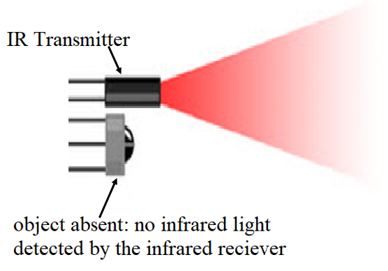
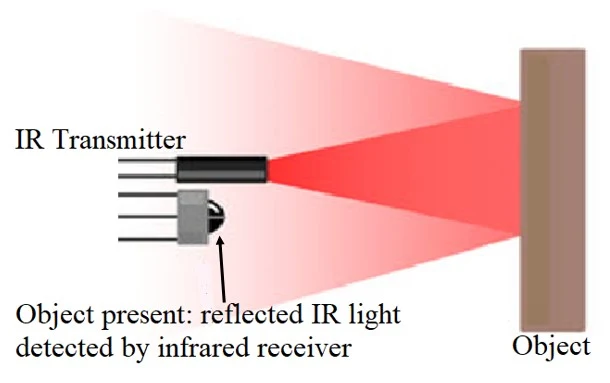
categorized as an Opto-coupler. The figure below illustrates on how the sensor
senses. |
| Illustration of sensing by IR sensor when no object is present |
 |
Illustration
of sensing by IR sensor when object is present
|
Obstacle Sensing Circuit or IR Sensor Circuit
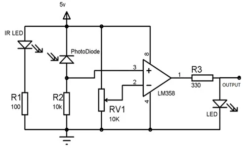
A typical IR sensing circuit consists of an IR LED
which emits infrared light, a photodiode which detects the infrared light, an IC
OPAM which is used as a voltage comparator, a potentiometer which is used to
calibrate the output of the sensor and a LED for signaling. This circuit is
shown below in the figure below.
 |
| IR Sensor circuit diagram |
The IR LED produces IR radiations and when the photodiode receives the reflected infrared radiations from an object, the resistance of the photodiode falls significantly. One of the input to the operational amplifier (LM358) is connected to the photodiode’s series resistor and the other input to the potentiometer which is set to a threshold value. When the incident radiation on the photodiode increases, the voltage drop across the series resistor will be high. The operational amplifier then compares the voltage across the series resistor to threshold voltage. If the voltage across the resistor in series with photodiode is greater than the threshold voltage set by the potentiometer, the output of the operational amplifier becomes high and the LED shines.
The IR LED can also be positioned directly in front of
the IR receiver such that almost all the radiations falls on the receiver, and
an object passing in-between this setup instead obstructs the radiation from
reaching the receiver. This method is called the direct incidence setup.