social

pop

Direct On Line Starter wiring diagram forward and reverse automatic starting

Direct On Line semi-automatic Starting forward and reversed rotation

Direct on line starting is a method generally used to start three phase induction motors with power less than or equal to 10KW.

Circuit diagram of direct on line starting:

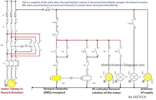
The circuit diagram is divided into the the Power Circuit and Control circuit shown below.
Direct on line semi automatic starting

Operating principle:

When the fuse isolator is closed, an action on the start push button S2 energises the contactor KM1 which closes the main contacts of the contactor, closes its hold on contact, opens the interlock on kM2 (so that KM2 should not be energized) and closes the open contact of KM1 to which the lamp H1 is connected. The motor rotates in the forward direction and the lamp H1 shines which indicates the motor is running in the forward direction.
Direct on line semi automatic starting forward and reverse
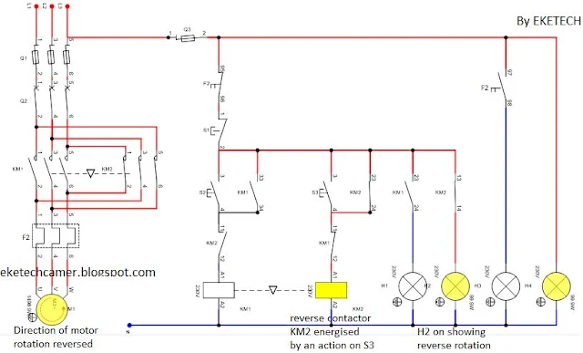
To reverse the direction of rotation of the motor, the motor must first be stopped by pressing S1.

For reverse rotation, an action on the reverse push button S3 energises the contactor KM2 which closes the main contacts of the contactor, closes its hold on contact, opens the interlock on KM1 (so that KM1 should not be energized) and closes the open contact of KM2 to which the lamp H2 is connected. The motor rotates in the reverse direction and the lamp H2 shines which indicates the motor is running in the reverse direction.
The chronogram below shows how the pulse created by push button S3 energizes the reverse contactor and puts ON H2.
Direct on line starter

Direct on line reversal
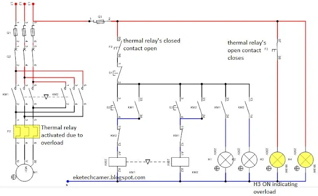
In case of prolonged overload, the thermal relay’s normally closed contact (NC F2) opens and the normally opened contact of F2 to which the lamp H3 is connected closes and the lamp shines which indicates the presence of the fault.

The lamp H4 indicates the presence of supply.
Direct on line starting two direction of rotation


Related and recommended:


Popular posts from this blog

Intermediate switch connection and wiring diagram

Intermediate switch An intermediate switch is a switch which permits the control of a lighting point from three positions. In order to control this lighting point from the three positions, the intermediate switch is connected together with two other 2-way switches. Application: it can be used in lighting a room or hall having 3 entrances , it can also be used in long corridors and staircases. We shall be looking at these connections. Connection diagram of intermediate switching Below is an illustration of the connection. The brown lines indicated on the diagram are the switching contacts. The switch labelled 2 is an intermediate switch . The figure below is the configuration of an intermediate switch. The switch labelled 1 and 3 in the first diagram are two-way switches.  Click here to know more about two-way switches . ON and OFF positions of intermediate switching ON positions OFF positions Staircase wiring layout using an inte...

PAST GCE QUESTIONS AND SOLUTIONS

 GCE PAST QUESTIONS AND SOLUTIONS TECHNICAL GCE ITVE and GCE ATVE Questions and Answers DOWNLOAD All ELECTRICAL POWER SYSTEM   DOWNLOAD All ELECTRONICS   DOWNLOAD All AIR CONDITIONING DOWNLOAD All MECHANICAL MANUFACTURING DOWNLOAD All AUTOMOBILE MECHANICS DOWNLOAD All SHEET METAL DOWNLOAD All WOOD WORKS    DOWNLOAD All BUILDING CONSTRUCTION DOWNLOAD All TOPOGRAPHY DOWNLOAD All CIVIL ENGINEERING DOWNLOAD All COMPUTER SCIENCE   DOWNLOAD All ICT DOWNLOAD All  ICT DOWNLOAD All CHEMICAL ENGINEERING DOWNLOAD All TOURISM DOWNLOAD All ACCOUNTING DOWNLOAD All  ICT DOWNLOAD All MATHEMATICS DOWNLOAD All LAW DOWNLOAD All ENGINEERING SCIENCE GENERAL EDUCATION GCE QUESTIONS AND SOLUTION DOWNLOAD All MATHEMATICS DOWNLOAD All FURTHER MATHEMATICS DOWNLOAD All ADDITIONAL MATHEMATICS DOWNLOAD All PHYSICS DOWNLOAD All BIOLOGY DOWNLOAD All HUMAN BIOLOGY DOWNLOAD All  ICT DOWNLOAD All CHEMISTRY DOWNLOAD All GEOGRAPHY DOWNLOAD All ECONOMICS DOWNLOAD All HISTORY D...

GCE QUESTIONS AND SOLUTIONS FOR ELECTRICAL POWER SYSTEMS

 DOWNLOAD GCE PAST QUESTIONS AND SOLUTIONS FOR EPS POWER ELECTRONICS  Download 1     Download 1b Download 2     Download 2b      Download 2C Download 3 AUTOMATIC CONTROL OF ELECTRICAL MACHINES Download 1 Download 2 Download 3      Download 3b Download 4      Download 4b    2020 DESIGN OF ELECTRICAL INSTALLATION Download 1 Download 2 Download 3      Download 3b      Download 3C      Download 3D CIRCUIT ANALYSIS Download 1 Download 2 Download 3 Download 4 ENGINEERING SCIENCE Download 1 2019 Download 2 2023 paper 1 Download 3   MOCK      Download 3B  Download 4         Download 5          Download 6 Download 7   ITV ELECTRICAL AND ELECTRONIC CIRCUIT  Download 1 ELECTRICAL DIAGRAM Download 1   CAP ELECTRICAL TECHNOLOGY AND DIAGRAM Download 1 Download 2   ITV...