Teleruptor (Teleswitch)
A teleruptor is an electrical device, which is used to control a lighting point from many positions (3, 4, 5, or
more) unlike one way or two way switches. This device has an advantage over an intermediate switch (which can only
control a lighting point from only 3 positions).
Push buttons are used at the various control points
to activate this device which puts on the lamp. We are going to see how to
connect this device. Before that, it is very important to know its area of
application.
Application: The above mentioned advantage, permits this device
to be used in: Long corridors, stair
case, and halls or rooms with more than 2 entrance.
Wiring a teleruptor
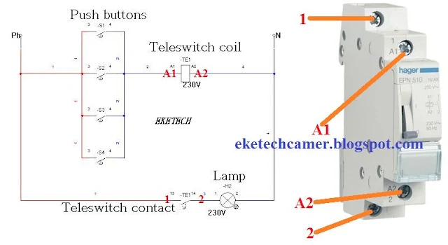
Below is a view of a teleruptor showing its contacts labeled and also indicated in the wiring diagram.
 |
| View of teleruptor and wiring |
The teleswitch is made up of a coil which energizes
or dis-energizes thereby closing or opening its contact respectively. It is
connected in such a way that, a pulse received from the push button causes
current to flow to the coil which energize or dis-energize the coil as
mentioned above.
 |
| wiring a teleswitch |
The lamp is connected at the output of the teleruptor’s contact such that, the lamp is supplied when the contact closes.
Operation: let's see how the lamp is put on from many positions.
An action on any of the push buttons ( S1, S2, S3, S4), creates a path for current to flow to the coil of the teleruptor thereby energizing it. As the teleruptor energizes, it closes its contact (TE1) to which the lamp is connected thereby supplying the lamp and the lamp shines.
For example in the figure below, push button S1 is pressed which creates the pathway for the current to flow. see below
 |
| How a teleswitch is energized |
Note that a push button does not remain in the closed state as seen above. A push button when pressed and released, closes and opens back immediately when released. Just that small time the push button is closed, is sufficient in energizing the teleswitch. So, the diagram below shows the exact state of the push button when pressed and released and the lamp comes ON.
 |
| Lamp ON when push button is pressed |
So the push button just gives a pulse to activate the teleruptor. The chronograph below shows the pulse produce by S1 when pressed, the pulse received by teleswitch's coil, and it's contact (ON-when pressed) and the state of the Lamp (H2).
 |
| chronogram showing energization of teleswitch by push button |
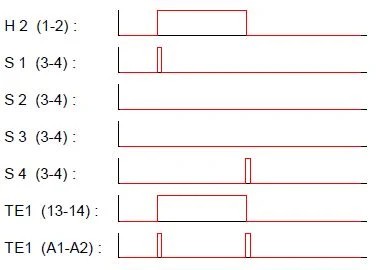
To put OFF the lamp, any push button can be pressed. For example pressing push button S4. we see from the figure below that lamp goes OFF. This is because, the pulse generated by pressing a push button again dis-energizes the coil which opens its contact thereby cutting OFF power to the teleswitch. see the figure and chronograph below.
 |
| Energizing and dis-energizing a teleruptor |
A clear view of the chronograph showing how an action on S4 dis-energizes the coil and the contact OFF, H2 OFF
 |
| Chronograph energizing and dis-energizing a teleruptor |
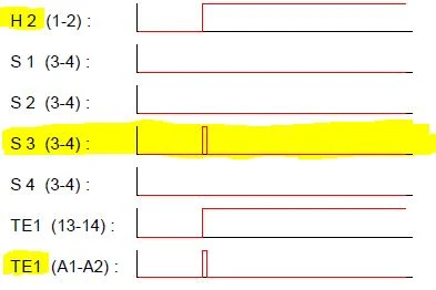
An action on any of the push button again puts on the lamp ON as earlier explained. For example pressing S3 puts the Lamp ON. see the chronograph below
 |
| chronograph push button S3 energizing the teleruptor |
By EKETECH
Related: