social

pop

Single phase induction motor operation and starting methods

Single phase induction motors

A single phase induction motors is a type of single phase motor

Constitution or parts

A single phase induction motor is made up of two main parts. Namely: the stator and the rotor and may include other accessories like centrifugal switch etc, capacitors.
Single phase induction motor
Internal view of a type of single phase induction motor with view of a centrifugal switch and capacitor

Stator: The stator carries single phase windings (main winding and start winding for starting). These windings are distributed ( uniform or equal distribution of the conductors in the slots).
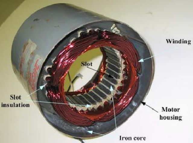
Stator of single phase induction motor
Stator of a single phase induction motor

Rotor: The rotor of a single phase induction motor is  of squirrel cage type (Squirrel Cage rotor)
Squirrel cage rotor of single phase induction motor
Squirrel cage rotor of a single phase induction motor
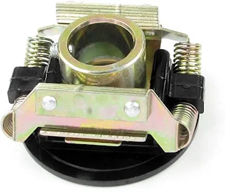
A centrifugal switch may also be incorporate into the motor ( connected in series with the starting winding) and is used to cut off the starting winding when the rotor accelerates to  about 75% of the rated speed.
This switch is usually mounted on the rotor's shaft.

Centrifugal switch
Centrifugal switch

Note: The starting winding is also called the auxiliary winding

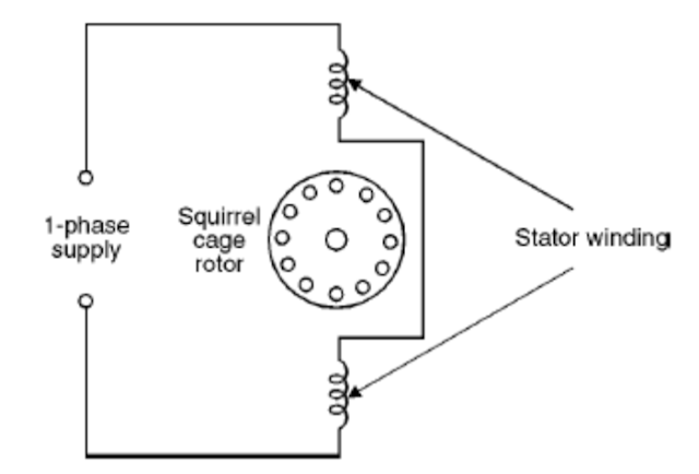
Representation

Let's see how we can represent the rotor and the stator.
Single phase induction motor representation
Representation of a single phase induction motor

Operating principle of single phase induction motors

Supplying the stator with single phase supply, causes current to flow through the stator conductor which creates an alternating magnetic field (flux) around it.  This flux is induced into the rotor and therefore, current flows in the rotor conductors and also produces a magnetic field. Despite the production of these two fields, the rotor does not rotate. This is because the magnetic field produced does not rotate but alternates. Consequently, a null (zero) resultant torque is produced which can not rotate rotor but only vibrates. So, a rotating magnetic field is necessary to produce a torque to rotate the rotor. That is why single phase induction motor are not self starting.
So, in order to start this motor,  a rotating magnetic field needs to  be created. This can be achieved by introducing a starting winding, which permits a 90 degrees phase shift to be created between the current in main winding and that in  starting winding.

Types of single phase induction motors (Starting methods)

The types of single phase induction motors are named based on their starting methods. They are:

  1. Split – phase Induction Motor
  2. Capacitor – Start Motor
  3. Permanent – Split Capacitor Motor
  4. Capacitor - Start Capacitor - Run
  5. Shaded Pole Induction Motor

Related and Recommended:


Popular posts from this blog

PAST GCE QUESTIONS AND SOLUTIONS

 GCE PAST QUESTIONS AND SOLUTIONS TECHNICAL GCE ITVE and GCE ATVE Questions and Answers DOWNLOAD All ELECTRICAL POWER SYSTEM   DOWNLOAD All ELECTRONICS   DOWNLOAD All AIR CONDITIONING DOWNLOAD All MECHANICAL MANUFACTURING DOWNLOAD All AUTOMOBILE MECHANICS DOWNLOAD All SHEET METAL DOWNLOAD All WOOD WORKS    DOWNLOAD All BUILDING CONSTRUCTION DOWNLOAD All TOPOGRAPHY DOWNLOAD All CIVIL ENGINEERING DOWNLOAD All COMPUTER SCIENCE   DOWNLOAD All ICT DOWNLOAD All  ICT DOWNLOAD All CHEMICAL ENGINEERING DOWNLOAD All TOURISM DOWNLOAD All ACCOUNTING DOWNLOAD All  ICT DOWNLOAD All MATHEMATICS DOWNLOAD All LAW DOWNLOAD All ENGINEERING SCIENCE GENERAL EDUCATION GCE QUESTIONS AND SOLUTION DOWNLOAD All MATHEMATICS DOWNLOAD All FURTHER MATHEMATICS DOWNLOAD All ADDITIONAL MATHEMATICS DOWNLOAD All PHYSICS DOWNLOAD All BIOLOGY DOWNLOAD All HUMAN BIOLOGY DOWNLOAD All  ICT DOWNLOAD All CHEMISTRY DOWNLOAD All GEOGRAPHY DOWNLOAD All ECONOMICS DOWNLOAD All HISTORY D...

Intermediate switch connection and wiring diagram

Intermediate switch An intermediate switch is a switch which permits the control of a lighting point from three positions. In order to control this lighting point from the three positions, the intermediate switch is connected together with two other 2-way switches. Application: it can be used in lighting a room or hall having 3 entrances , it can also be used in long corridors and staircases. We shall be looking at these connections. Connection diagram of intermediate switching Below is an illustration of the connection. The brown lines indicated on the diagram are the switching contacts. The switch labelled 2 is an intermediate switch . The figure below is the configuration of an intermediate switch. The switch labelled 1 and 3 in the first diagram are two-way switches.  Click here to know more about two-way switches . ON and OFF positions of intermediate switching ON positions OFF positions Staircase wiring layout using an inte...

GCE QUESTIONS AND SOLUTIONS FOR ELECTRICAL POWER SYSTEMS

 DOWNLOAD GCE PAST QUESTIONS AND SOLUTIONS FOR EPS POWER ELECTRONICS  Download 1     Download 1b Download 2     Download 2b      Download 2C Download 3 AUTOMATIC CONTROL OF ELECTRICAL MACHINES Download 1 Download 2 Download 3      Download 3b Download 4      Download 4b    2020 DESIGN OF ELECTRICAL INSTALLATION Download 1 Download 2 Download 3      Download 3b      Download 3C      Download 3D CIRCUIT ANALYSIS Download 1 Download 2 Download 3 Download 4 ENGINEERING SCIENCE Download 1 2019 Download 2 2023 paper 1 Download 3   MOCK      Download 3B  Download 4         Download 5          Download 6 Download 7   ITV ELECTRICAL AND ELECTRONIC CIRCUIT  Download 1 ELECTRICAL DIAGRAM Download 1   CAP ELECTRICAL TECHNOLOGY AND DIAGRAM Download 1 Download 2   ITV...