social

pop

WHAT IS A MULTIPLEXER?

 MULTIPLEXER

we are going to see more complex combinational logic circuits or combinational devices which are the multiplexer and demultiplexer. These devices are can be found as integrated circuits (ICs) and are widely used in the field of telecommunication like in multiplexing.

WHAT IS A MULTIPLEXER?

A multiplexer also called data selector is a device that selects one of many input signals and forwards the selected input to the output. A multiplexer of 2n inputs has n select bits, which are used to select which input line to send to the output.  See figure 1.

An electronic multiplexer makes it possible for several signals to share one device or resource like one communication line instead of having one device per input signal. An example can be in a cyber where many computers are connected to the same printer, another example is an mp3 player, laptop, digital cable TV connected to a single surrounding sound system through a Mux.

multiplexer block representation 

2 DATA INPUT MULTIPLEXER

A two 2 to 1-line multiplexer have; 2 inputs, 1 select input and 1 output. 4 data inputs, 2 select input and 1 output.

2 data input multiplexer 

An example is the 74LS157 quad 1-of-2 data selector IC, shown in figure below 

74LS157 quad 1of 2 data selector (multiplexer) IC  

TRUTH TABLE OF A 2 TO 1 LINE MULTIPLEXER

 Below is the truth table of a 2 to 1 line data selector

truth table of a 2 data input multiplexer data selector 

Boolean expression of the output of a 2 to 1 multiplexer

This expression is obtained from the truth table above

 Boolean expression of a 2 data input multiplexer

Logic circuit of a 2 to 1 line Multiplexer

Hence, using the boolean expression above, we obtain the logic circuit below

2 data input Multiplexer logic circuit

   4 TO 1 LINE MULTIPLEXER

A 4-data multiplexer have; 4 data inputs, 2 select input and 1 output.

4 data input multiplexer

4 data input multiplexer                  

Example: using the figure above we are going to implement a 4 data multiplexer

TRUTH TABLE OF A 4 TO 1 LINE MULTIPLEXER

 Below is the truth table of a 4 to 1 line data selector

TRUTH TABLE OF A 4 TO 1 LINE MULTIPLEXER

The Boolean expression of the output from the truth table is given by

Boolean expression of 4 to 1 data multiplexer
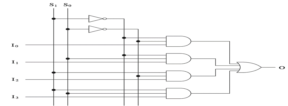
Hence, from the Boolean expression we obtain the logic circuit below
logic circuit of a 4 data input multiplexer

Implementation of a 4-data input multiplexer.


8 DATA INPUT MULTIPLEXER

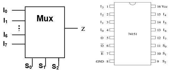
An 8-line to 1-line multiplexer has 8 data inputs, 3 select input and 1 output. This is shown in figure below. An example of an 8 data multiplexer IC is the 74151 shown in fig below with its pin configuration.

8 data input multiplexer

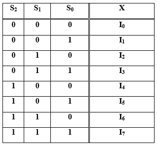
Truth table of an 8 data input multiplexer

The corresponding Truth table of the 8 data input multiplexer is given below

Truth table of an 8 data input multiplexer

From the truth table above, the Boolean expression of the 8 data input multiplexer is given below

Boolean expression of an 8 data input multiplexer

Logic circuit of an 8 data input multiplexer

Hence, we obtain the logic circuit below

logic circuit of an 8 data input multiplexer
Implementation of an 8 data multiplexer.


Popular posts from this blog

PAST GCE QUESTIONS AND SOLUTIONS

 GCE PAST QUESTIONS AND SOLUTIONS TECHNICAL GCE ITVE and GCE ATVE Questions and Answers DOWNLOAD All ELECTRICAL POWER SYSTEM   DOWNLOAD All ELECTRONICS   DOWNLOAD All AIR CONDITIONING DOWNLOAD All MECHANICAL MANUFACTURING DOWNLOAD All AUTOMOBILE MECHANICS DOWNLOAD All SHEET METAL DOWNLOAD All WOOD WORKS    DOWNLOAD All BUILDING CONSTRUCTION DOWNLOAD All TOPOGRAPHY DOWNLOAD All CIVIL ENGINEERING DOWNLOAD All COMPUTER SCIENCE   DOWNLOAD All ICT DOWNLOAD All  ICT DOWNLOAD All CHEMICAL ENGINEERING DOWNLOAD All TOURISM DOWNLOAD All ACCOUNTING DOWNLOAD All  ICT DOWNLOAD All MATHEMATICS DOWNLOAD All LAW DOWNLOAD All ENGINEERING SCIENCE GENERAL EDUCATION GCE QUESTIONS AND SOLUTION DOWNLOAD All MATHEMATICS DOWNLOAD All FURTHER MATHEMATICS DOWNLOAD All ADDITIONAL MATHEMATICS DOWNLOAD All PHYSICS DOWNLOAD All BIOLOGY DOWNLOAD All HUMAN BIOLOGY DOWNLOAD All  ICT DOWNLOAD All CHEMISTRY DOWNLOAD All GEOGRAPHY DOWNLOAD All ECONOMICS DOWNLOAD All HISTORY D...

Intermediate switch connection and wiring diagram

Intermediate switch An intermediate switch is a switch which permits the control of a lighting point from three positions. In order to control this lighting point from the three positions, the intermediate switch is connected together with two other 2-way switches. Application: it can be used in lighting a room or hall having 3 entrances , it can also be used in long corridors and staircases. We shall be looking at these connections. Connection diagram of intermediate switching Below is an illustration of the connection. The brown lines indicated on the diagram are the switching contacts. The switch labelled 2 is an intermediate switch . The figure below is the configuration of an intermediate switch. The switch labelled 1 and 3 in the first diagram are two-way switches.  Click here to know more about two-way switches . ON and OFF positions of intermediate switching ON positions OFF positions Staircase wiring layout using an inte...

GCE QUESTIONS AND SOLUTIONS FOR ELECTRICAL POWER SYSTEMS

 DOWNLOAD GCE PAST QUESTIONS AND SOLUTIONS FOR EPS POWER ELECTRONICS  Download 1     Download 1b Download 2     Download 2b      Download 2C Download 3 AUTOMATIC CONTROL OF ELECTRICAL MACHINES Download 1 Download 2 Download 3      Download 3b Download 4      Download 4b    2020 DESIGN OF ELECTRICAL INSTALLATION Download 1 Download 2 Download 3      Download 3b      Download 3C      Download 3D CIRCUIT ANALYSIS Download 1 Download 2 Download 3 Download 4 ENGINEERING SCIENCE Download 1 2019 Download 2 2023 paper 1 Download 3   MOCK      Download 3B  Download 4         Download 5          Download 6 Download 7   ITV ELECTRICAL AND ELECTRONIC CIRCUIT  Download 1 ELECTRICAL DIAGRAM Download 1   CAP ELECTRICAL TECHNOLOGY AND DIAGRAM Download 1 Download 2   ITV...