social

pop

Interfacing a relay using a microcontroller

Interfacing a relay circuit with a PIC microcontroller

We are going to see how to interface a relay to a PIC micro controller. But before that, you need to know what is a relay.
A relay is a switching device which permits the switching of a load in a circuit or to a supply. The advantage of using a relay is due to the fact that, this device can permit the switching of high loads in circuits.
Before interfacing a relay in a circuit, the relay must be chosen to suit the supplying circuit and the required load. For example, there are relays which operate at 5V, 6V, 12V, etc. and having a maximum load current and voltage rating.

Materials

PIC 16F877A, 5V relay, 5V DC source, 1 BC547 transistor, 1 diode 1N4148, 230V AC load (heater), 230V AC source, 8MHz Crystal Oscillator, 2 ceramic capacitors, 2 resistors, 1 push button.

Circuit diagram of relay with microcontroller

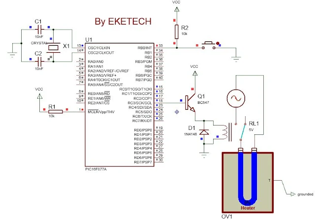
The circuit diagram is shown below.

interfacing a relay
The relay is connected to PORTC of the microcontroller at Pin RC3.

The push button to activate the relay which switches on the load is connected to PORTB of the microcontroller at Pin RB0.
A flyback diode is connected to the relay to protect it against back emf.

 Interfacing a relay with microcontroller Code

This code is written in C with the software: mikroC pro.
See the image of the code below
code interfacing a relay
You can copy the code below
void main() {
TRISB=0xFF;
TRISC=0x00;
PORTC=0X00;
while(1) {
if (PORTB.RB0==0)
     {PORTC.RC3=1;}
else {PORTC.RC3=0;}
         }
            }

Explanation of Code

TRISB = 0XFF; means configuring PORTB as input (FF means 1111 1111 in digital)
TRISC=0x00; means configuring PORTC as output (00 means 0000 0000 in digital)
PORTC=0X00; means putting PORTC OFF (initialized)
while(1) { some code here} means taking a loop. The code in the braces is executed infinitely.
if (PORTB.RB0 = =0) {PORTC.RC3=1;} means if Pin RB0 is pressed (Pin is at logic 0), put on the relay connected to Pin RC3.
else {PORTC.RC3=0;} means if Pin RB0 is not pressed (Pin is at logic 1), put OFF the relay connected to Pin RC3.
Once the code is imported into the PIC microcontroller, the system behaves as such:

The relay is initially OFF. Hence the heater OFF (blue).  See below
interfacing a relay with PIC microcontroller


Once the push button connected to Pin RB0 is pressed, the relay is activated switches the load to the 230V supply and the heater is ON and starts heating. See below

The heater heated to 75%


interfacing a relay with microcontroller


Heater heated to 100%

Interfacing a relay with PIC microcontroller


When the push button is pressed again, the relay is disactivated and switches of the load (heater).

Related: 


Interfacing 16x2 LCDInterfacing 16x4 LCDScrolling text on LCD


Interfacing infrared distance sensor

Interfacing a pH meter


Popular posts from this blog

How to Install Proteus 8 Professional: A Step-by-Step Guide

 How to Install Proteus 8 Professional: A Step-by-Step Guide Proteus 8 Professional is a powerful tool for electronic circuit design and simulation. Whether you’re a student, hobbyist, or professional engineer, following a clear installation process ensures you get started without headaches. Are you ready to start designing and simulating electronic circuits with Proteus 8 Professional!   Here’s a comprehensive, guide to installing Proteus 8 Professional on your Windows PC. Step 1: Download the Installer ·        Visit the official Labcenter Electronics website or another trusted source to download the Proteus 8 Professional installer. Avoid unofficial sources to prevent malware or corrupted files . You can download from HERE DOWNLOAD PROTEUS AND ARDUINO ·        The installer typically comes as a ZIP file. Wait for the download to finish and locate it in your Downloads folder Step 2: Extract the Installer...

Intermediate switch connection and wiring diagram

Intermediate switch An intermediate switch is a switch which permits the control of a lighting point from three positions. In order to control this lighting point from the three positions, the intermediate switch is connected together with two other 2-way switches. Application: it can be used in lighting a room or hall having 3 entrances , it can also be used in long corridors and staircases. We shall be looking at these connections. Connection diagram of intermediate switching Below is an illustration of the connection. The brown lines indicated on the diagram are the switching contacts. The switch labelled 2 is an intermediate switch . The figure below is the configuration of an intermediate switch. The switch labelled 1 and 3 in the first diagram are two-way switches.  Click here to know more about two-way switches . ON and OFF positions of intermediate switching ON positions OFF positions Staircase wiring layout using an inte...

GCE Syllabus and Scheme of work Cameroon technical and general schools

Syllabus Electrical Technology ( for Electrotechnics, Electronics and Air-conditioning), Mechanical ( Automobile, sheet metal ), civil engineering (plumbing, wood works, building and public works), tailoring General education is also available down In Cameroon, a syllabus  is a guideline defining the structure and the content of a course. Have you be searching for this? Your problem is solved Download is available at the bottom page The scheme of work is a guide used to monitor the progress of a course based on an original plan. Hence it can be viewed as interpretation of a syllabus.  Teachers use it as a harmonised guide in a particular territory like in Cameroon, in order to attain the same general and specific objectives all over the educational institutions. Speciality include: Electrotechnics Electronics  Air-conditioning Title of module (Subjects): Electricity/Electronics. Its is commonly called in Cameroon ELEC-ELO Technology and Electrical...